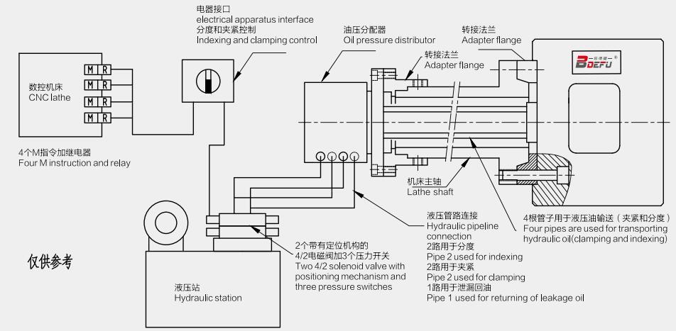
Installation and connection diagram for automatic index chuck.

Technical characteristics
Trisection, quartering swap function (one unit can realize two functions).
One-time clamping can complete the processing of several working faces, which can directly improve processing efficiency 6-10 times.
High positioning precision and repeated positioning precision.
Long-term lubrication characteristics of internal institutions ensure reliable indexing performance and anti-jamming system.
Control is continuous and automatic, and processing is very safe.
The clamping of workpiece is of high speed and rigidity, and allow large cutting quantity.
The centrifugal force compensation system (confirm when ordering).
Indexing position to level monitoring system (confirm when ordering).
Special function
After quenching and grinding, the design of deformation resistance can effectively ensure the stiffness and precision.
In the process of shaft spindling, can carry out indexing operation ,and fast conversion of several working shaft is allowed.
Indexing and holding mechanism is of uninterrupted oil lubrication, and supported by strong import bearings.
To achieve higher production efficiency , the centrifugal force compensation system is adopted under the high limit speed.
Hydraulic system is very simple with only four oil pipes, of which two are used for indexing mechanism and two for holding mechanism.
Through the lathe CNC system or independent electrical apparatus interface, control the workpiece’s processing position and other parameters continuously automatically.
Internal mechanism is completely sealed to fully prevent the pollutants’ entering of cutting fluid,waste, and dust.
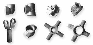
Small parts

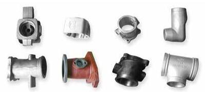
Medium parts

Large parts

Performance parameters
Can achieve indexing angle of 4x90°,8X45°,3x120°,6x60°and special angle.
| Dim/Spec | KFD-168 | KFD-210 | KFD-235 | KFD-250 | KFD-280 | KFD-315 | KFD-360 | KFD-400 | KFD-460 | KFD-570 | KFD-680 |
| A | mm | 172 | 215 | 235 | 254 | 275 | 315 | 360 | 400 | 460 | 570 | 680 |
| B | mm | 140 | 170 | 170 | 220 | 220 | 220 | 220 | 300 | 300 | 380 | 380 |
| C | mm | 104.8 | 133.4 | 133.4 | 171.4 | 171.4 | 171.4 | 171.4 | 235 | 235 | 330.2 | 330.2 |
| D | mm | 11 | 13 | 13 | 17 | 17 | 17 | 17 | 21 | 21 | 27 | 27 |
The maximum axial
loading window | G | mm | 125 | 175 | 197 | 216 | 239 | 261 | 301 | 333 | 395 | 466 | 576 |
| H | mm | 152 | 180 | 190 | 210 | 218 | 235 | 260 | 291 | 321 | 435 | 485 |
| I | mm | 2 | 3 | 3 | 3 | 3 | 3 | 3 | 3 | 3 | 5 | 5 |
| P | mm | 30 | 35 | 35 | 44 | 45 | 50 | 50 | 58 | 58 | 85 | 85 |
| Q | mm | 46 | 95 | 102 | 112 | 125 | 136 | 150 | 170 | 200 | 270 | 320 |
| R | mm | 33 | 48 | 40 | 46 | 58 | 82 | 100 | 110 | 140 | 180 | 235 |
| T | mm | 33 | 36 | 53 | 56 | 70 | 66 | 88 | 91 | 121 | 150 | 205 |
| Jaw stroke | U | mm | 9 | 15 | 15 | 17 | 17 | 23 | 23 | 30 | 30 | 40 | 40 |
| V | mm | M8 | M8 | M8 | M8 | M8 | M10 | M10 | M10 | M10 | M10 | M10 |
| W | mm | 18 | 20 | 25 | 25 | 25 | 25 | 25 | 25 | 25 | 50 | 50 |
| Y | mm | 5 | 6 | 8 | 10 | 12 | 12 | 12 | 12 | 12 | 18 | 18 |
| Z | mm | 30 | 28 | 28 | 32 | 32 | 29 | 29 | 24 | 24 | 50 | 50 |
| Piston area |
| cm2 | 13 | 30 | 30 | 43 | 43 | 63.6 | 63.6 | 86.6 | 86.6 | 113 | 113 |
| Maximum pressure |
| bar | 25 | 35 | 35 | 35 | 35 | 35 | 35 | 35 | 35 | 35 | 35 |
| Maximum speed |
| r.p.m | 3000 | 3000 | 2800 | 2500 | 2200 | 2000 | 1700 | 1200 | 1000 | 800 | 600 |
| Rotating moment |
| kg.m2 | 0.12 | 0.16 | 0.27 | 0.47 | 0.88 | 1.45 | 2.05 | 3.4 | 6.4 | 12 | 29 |
| Clamping jaw weight |
| kg | 0.5 | 0.6 | 0.6 | 1.3 | 1.3 | 2 | 2 | 4 | 5 | 6 | 7 |
| Body weight |
| kg | 18 | 24 | 32 | 42 | 52 | 80 | 95 | 128 | 170 | 285 | 490 |
*Note:
Only in the maximum pressure, the highest speed can be achieved when using the jaw of no more than the weight shown in the table above.
The processed workpieces and two jaws must be well balanced rotating the axis. If do not meet this condition, or jaw is overweight, the speed must be reduced.
The workpiece can index when the shaft is rotating. When the workpiece at high speed, to avoid vibration as a result of workpiece’ weight unbalance in the middle position, the speed is proposed to reduce 30-50%.
Türkçe
English
Русский
繁體中文
العربية
Français
Español
Português
Deutsch
italiano
日本語
한국어
Nederlands
Tiếng Việt
ไทย
Polski
ພາສາລາວ
ភាសាខ្មែរ
Bahasa Melayu
ဗမာစာ
தமிழ்
Filipino
Bahasa Indonesia
magyar
Română
Čeština
қазақ
Српски
हिन्दी
فارسی
Slovenčina
Slovenščina
Norsk
Svenska
українська
Ελληνικά
Suomi
עברית
Latine
Dansk
اردو
বাংলা
Hrvatski
Afrikaans
Gaeilge
Māori
नेपाली
Oʻzbekcha
latviešu
Беларуская мова
Български
íslenska
Lietuvių


