Availability: | |
---|---|
Adjustable jaw
Claw compensation clamping
Adjust the end face driver by wedge block fixed tip or spring tip
Internal part surface quenching
Long-lasting lubricating grease
Completely sealed/low repair rate
Shaft processing chuck without end face driving
Mounting screw
Not include oil cylinder and other installation accessories
Center Tip Positioning At Axial Direction - End Face Drive By Power Driving
Double Piston Oil Cylinder Drive Model: RDN
Positioning based on work piece surface at axial direction - spring driven end face drive
Big Stroke Oil Cylinder Drive Model: RS-N
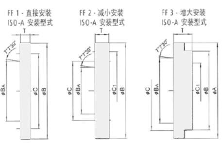
ISO-A coupling disc for SG chuck
SG chuck specification | main shaft | types | A | B | BA | C | C1 | T |
200 | A5 | 2 | - | 170 | 82.563 | 104.38 | 146 | 24 |
200 | A6 | 2 | - | 170 | 106.375 | 133.4 | 146 | 24 |
200 | A8 | 3 | 210 | 170 | 139.719 | 171.4 | 146 | 40 |
250 | A6 | 2 | - | 220 | 106.375 | 133.4 | 171.4 | 24 |
250 | A8 | 1 | - | 220 | 139.719 | 171.4 | - | 19 |
250 | A11 | 3 | 280 | 220 | 196.869 | 235 | 171.4 | 45 |
320 | A8 | 2 | - | 280 | 139.719 | 171.4 | 235 | 30 |
320 | A11 | 1 | - | 280 | 196.869 | 235 | - | 21 |
BDF-AUTOCHACK Model | SG-200 | SG-250 | SG-320 | ||
A | mm | 218 | 268 | 320 | |
B | mm | 170 | 220 | 280 | |
C | mm | 146 | 171.4 | 235 | |
D | mm | 17 | 17 | 21 | |
E | mm | 52 | 62 | 75 | |
F | mm | M38x1.5 | M50x1.5 | M55x2 | |
H | mm | 168 | 202 | 233 | |
L min. | mm | 24 | 35 | 31.2 | |
L max. | mm | 84 | 107 | 99 | |
R | mm | 69 | 86 | 105 | |
Claw angle stroke | U | deg. | 5° | 5° | 5° |
YF | mm | 9 | 10 | 10 | |
Z min. | mm | 78 | 78.5 | 73.5 | |
Z max. | mm | 150 | 156.8 | 156.8 | |
b | mm | 24 | 25 | 21.5 | |
f | mm | 4 | 5 | 5 | |
g | mm | 20 | 20 | 20 | |
Reference height | h | mm | 80 | 100 | 84 |
m1 | mm | M10 | M12 | M12 | |
m2 | mm | M8 | M10 | M12 | |
m3 | mm | M6 | M6 | M | |
n H7 | mm | 12 | 15 | 15 | |
a | deg. | 3° | 3° | 3° | |
Claw angle stroke | deg . | 5° | 5° | 5° | |
Claw radial stroke--height h | mm | 9 | 10 | 11.5 | |
Compensation amount--height h | mm | ±0.8 | ±1 | ±1 | |
Inclined wedge stroke (all) | mm | 58 | 66 | 80 | |
The biggest push & pull force | kN | 40 | 60 | 80 | |
Maximum clamping force - height h k | kN | 40 | 65 | 100 | |
Highest rotating speed | r.p.m. | 3000 | 2500 | 2000 | |
Quality (excluding claw) | kg | 30 | 55 | 100 | |
rotational inertia | kgm2 | 0.15 | 0.46 | 1.28 | |
Recommended driving oil cylinder - centering by central hole | RDN 125/30 80/25 | RDN 125/30 80/25 | RDN 150/40 95/25 | ||
centering by work piece surface | RS125N | RS125N | RS150N |
The above data are the standard parameters, personalized customized solutions can be provided according to customer's requirement.