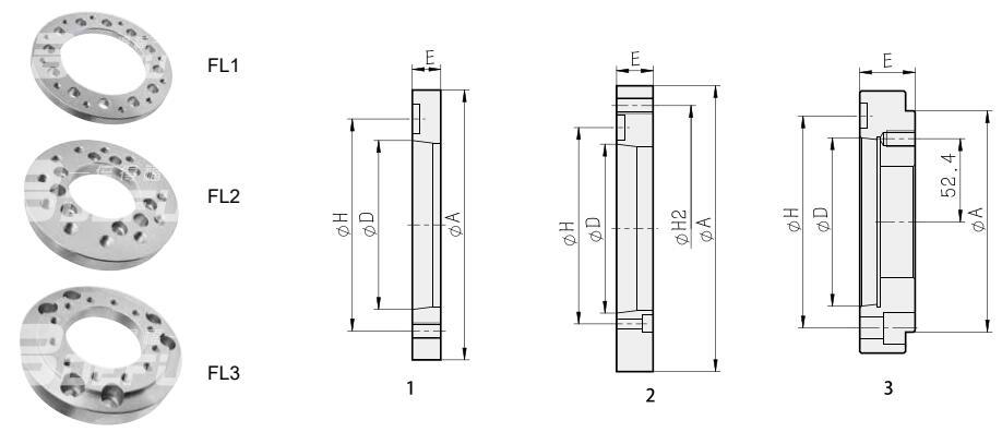
The flange usually has a circular shape with bolt holes around its perimeter to allow for easy and secure attachment to the chuck and the pneumatic system. The bolt holes are typically aligned with corresponding holes on the chuck and the pneumatic system to ensure a proper fit and alignment.
The pneumatic chuck connection flange is designed to provide a tight and secure connection between the chuck and the pneumatic system, allowing for efficient and reliable operation of the chuck. It plays a critical role in maintaining the stability and accuracy of the chuck during machining or other operations.
Overall, the pneumatic chuck connection flange is an essential component in pneumatic systems that use chucks, providing a reliable and secure connection between the chuck and the rest of the system.
Size parameter
| Spec. | A | B | C | D | E | F | G | H | I | J |
| KS05-3-A4 | 63.513 | 135 | 95 | 4.5 | 23.5 | 17 | 115 | 82.6 | 3-M8 | 3-M10X20 |
| KS06-3-A5 | 82.563 | 172 | 154 | 4.5 | 28.5 | 22 | 154 | 104.8 | 3-M8 | 6-M10X30 |
| KS08-3-A6 | 106.375 | 210 | 165 | 4.5 | 28.5 | 22 | 186 | 133.4 | 3-M10 | 6-M12X30 |
| KS10-3-A8 | 139.719 | 254 | 206 | 4.5 | 33.5 | 27 | 230 | 171.4 | 3-M12 | 6-M16X35 |
| KS12-3-A8 | 139.719 | 315 | 270 | 4.5 | 33.5 | 27 | 290 | 171.4 | 3-M12 | 6-M16X35 |
The above data are the standard parameters, personalized customized solutions can be provided according to customer's requirement.
Flange connecting diagram

| Size/Spec. | Nose of Spindle
D | A | H | H2 | E | Reference Drawing |
| 05A24 | A24 | 110 | 82.6 | - | 20 | Fig.1 |
| 06A25 | A25 | 140 | 104.8 | - | 15 | Fig.1 |
| 08A26 | A26 | 170 | 133.4 | - | 17 | Fig.1 |
| 10A28 | A28 | 220 | 171.4 | - | 18 | Fig.1 |
| 12A28 | A28 | 220 | 171.4 | - | 18 | Fig.1 |
| 15A211 | A211 | 300 | 235 | - | 22 | Fig.1 |
| 18A211 | A211 | 300 | 235 | - | 22 | Fig.1 |
| 21A215 | A215 | 380 | 330.2 | - | 27 | Fig.1 |
| 24A220 | A220 | 520 | 463.6 | - | 27 | Fig.1 |
| 32A215 | A215 | 380 | 330.2 | - | 27 | Fig.1 |
| 40A215 | A215 | 380 | 330.2 | - | 27 | Fig.1 |
| 04A24 | A24 | 85 | 82.6 | 70.6 | 40 | Fig.3 |
| 05A25 | A25 | 110 | 104.8 | 82.6 | 45 | Fig.3 |
| 06A24 | A24 | 140 | 82.6 | 104.8 | 20 | Fig.2 |
| 06A26 | A26 | 140 | 133.4 | 104.8 | 40 | Fig.3 |
| 08A25 | A25 | 170 | 104.8 | 133.4 | 24 | Fig.2 |
| 08A28 | A28 | 170 | 171.4 | 133.4 | 45 | Fig.3 |
| 10A26 | A26 | 220 | 133.4 | 171.4 | 28 | Fig.2 |
| 12A26 | A26 | 220 | 133.4 | 171.4 | 28 | Fig.2 |
| 12A211 | A2II | 220 | 235 | 171.4 | 54 | Fig.3 |
| 15A28 | A28 | 300 | 171.4 | 235 | 33 | Fig.2 |
| 18A28 | A28 | 300 | 171.4 | 235 | 33 | Fig.2 |
| 21A28 | A28 | 380 | 171.4 | 330.2 | 41 | Fig.2 |
| 21A211 | A2II | 380 | 235 | 330.2 | 41 | Fig.2 |
| 24A211 | A211 | 520 | 235 | 463.6 | 42 | Fig.2 |
| 24A215 | A215 | 520 | 330.2 | 463.6 | 42 | Fig.2 |
| 32A211 | A211 | 380 | 235 | 330.2 | 41 | Fig.2 |
| 40A211 | A211 | 380 | 235 | 330.2 | 41 | Fig.2 |

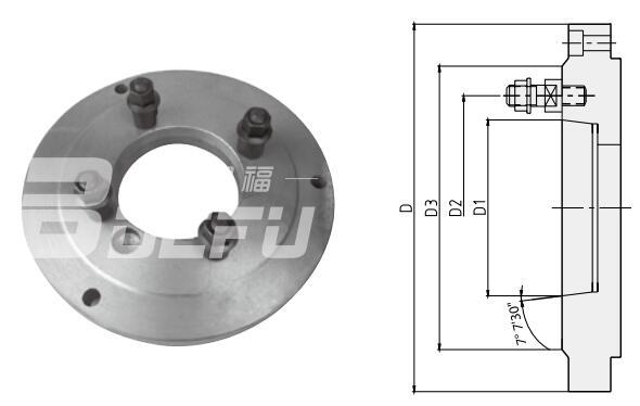
Type C
| No. | 3 | 4 | 5 | 6 | 8 | 11 | 15 |
| D1 | 53.975 | 63.513 | 82.563 | 106.375 | 139.719 | 196.869 | 285.775 |
| D2 | 75 | 85 | 104.78 | 133.35 | 171.45 | 235 | 330.2 |
| D3 | 102 | 112 | 135 | 170 | 220 | 290 | 400 |

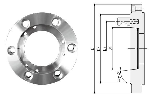
Type D
| No. | 3 | 4 | 5 | 6 | 8 | 11 | 15 |
| D1 | 53.975 | 63.513 | 82.563 | 106.375 | 139.719 | 196.869 | 285.775 |
| D2 | 70.6 | 82.563 | 104.78 | 133.35 | 171.45 | 235 | 330.2 |
| D3 | 92 | 117 | 146 | 181 | 225 | 298 | 403 |
The above data are the standard parameters, personalized customized solutions can be provided according to customer's requirement
Türkçe
English
Русский
繁體中文
العربية
Français
Español
Português
Deutsch
italiano
日本語
한국어
Nederlands
Tiếng Việt
ไทย
Polski
ພາສາລາວ
ភាសាខ្មែរ
Bahasa Melayu
ဗမာစာ
தமிழ்
Filipino
Bahasa Indonesia
magyar
Română
Čeština
қазақ
Српски
हिन्दी
فارسی
Slovenčina
Slovenščina
Norsk
Svenska
українська
Ελληνικά
Suomi
עברית
Latine
Dansk
اردو
বাংলা
Hrvatski
Afrikaans
Gaeilge
Māori
नेपाली
Oʻzbekcha
latviešu
Беларуская мова
Български
íslenska
Lietuvių


